
Cuts
The Cuts accordion, in the left column of the Model Splitter, is where you decide where the model comes apart. There are several kinds of cut: flat planes and grids of planes; the Cut tools, which cut along a line or a shape you draw over the model; cutting solids (a box, cylinder, sphere or one of your own meshes) whose inside becomes a part; and seams, loops laid on the surface that cut round an arm, a neck or a panel line. Every cut stays editable. Move a plane, resize a box or switch a cut off at any time, and the parts are worked out again from the whole model.
How cuts work
Nothing is cut until you press Apply Cut at the bottom of the accordion, or Return. Until then you can add, move and change cuts freely, and the parts stay as they were. Apply Cut also turns a shape you have marked with a Cut tool into its cut, and closes a Band or Rope you left open back to its anchor. When the parts are up to date, the button is greyed out.
- Each cut appears in the list under the cut buttons. Click its name to select it, and its settings open below the list.
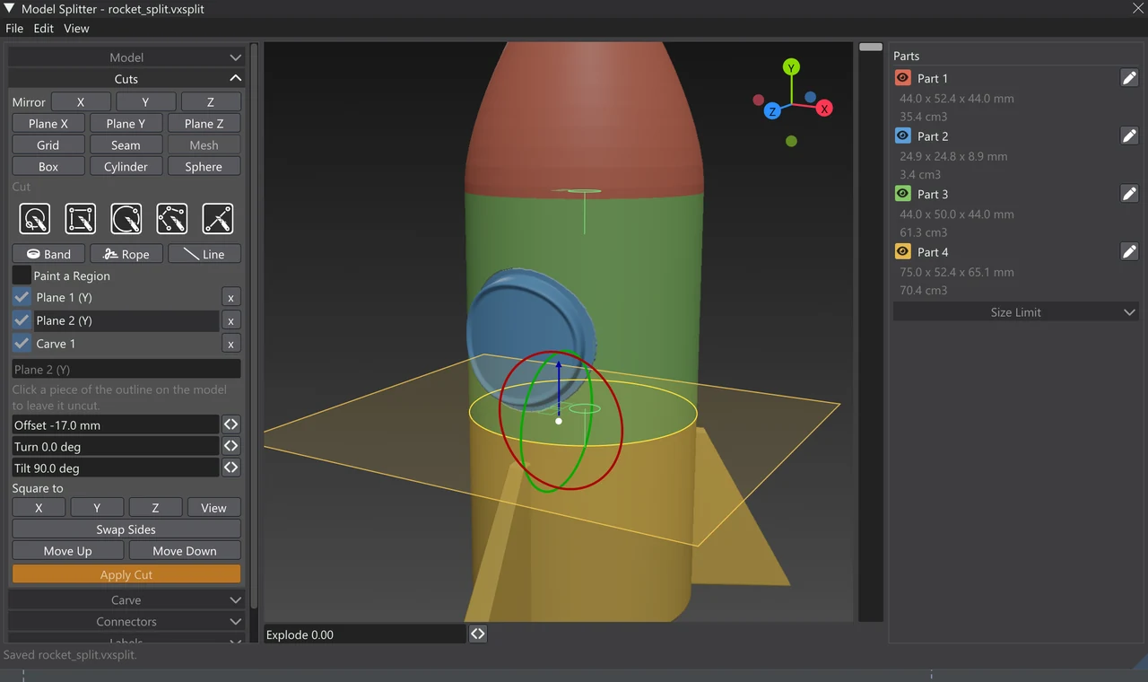
- A plane is drawn in the view only while it is selected: its square, its outline across the model and its gizmo. A cutting solid is drawn the same way. Apply Cut leaves nothing selected, so you see the finished parts clearly.
- Making a cut puts its tool away. Pick the tool again for the next cut.
- To get back to a plane after cutting, pick one of its parts in the Parts list on the right. That selects a plane cut the part has a face on.
Cuts are made in the order of the list, and each cut works on the parts the cuts above it made. Move Up and Move Down, at the bottom of a selected cut’s settings, change the order.
Planes
Plane X, Plane Y and Plane Z each add a flat cut through the model’s centre, square to that axis. Plane Y is a level cut: use it to take the top off a model or cut a figure at the waist. A new plane is selected as it is made.
The gizmo
A selected plane carries a gizmo in the view. Drag its arrow to slide the plane along its own direction, and drag one of its rings to turn the plane. The rings take a press a little outside them, so you need not hit the line exactly. Each drag is one undo step. While a drawing tool (a Cut tool, the brush, Band, Rope or Line) is out, the gizmo stands aside so it does not catch your strokes.
A plane’s settings
| Control | What it does |
|---|---|
| Name | The text field at the top. Leave it empty for the default name (“Plane 1”). |
| Offset | Where the plane sits along its own direction, in mm from the model’s centre. |
| Turn | Turns the plane round the up axis: 0° is square to X, 90° square to Z. |
| Tilt | Tilts the plane up out of the ground: 90° is square to Y, a level cut. |
| Square to X / Y / Z / View | Turns the plane square to that axis, or to face you in the view. It stays where it is. |
| Swap Sides | Turns the plane round, so its A side becomes B. This only changes the parts’ names and which side a peg goes on. |
| Only Where It Was Drawn | Shown for a plane made with Slice. Untick it to cut everything the plane passes through. |
You can type into any of these fields as well as drag them. Lengths can be typed in other units (“1 in”, “2.5 cm”) and are turned into millimetres.
Leaving pieces of a plane uncut
A plane often passes through more than one piece of the model: both legs of a figure, or the fins of a rocket as well as its body. The selected plane’s outline is split into those pieces. To keep one of them whole, click its outline on the model:
- Hover over the outline and the piece under the mouse lights up. Click it and it turns red and thin, which means that piece will not be cut. Click it again to cut it after all.
- The plane’s settings say how many pieces are left uncut. Cut Every Piece puts them all back.
- A piece left uncut keeps everything on both sides of it joined. A cut that does not go all the way round something cannot split it.
This works with no tool out and with the parts together (Explode at 0). Each click is one undo step, and like any change it waits for Apply Cut.
Grids and the size limit
Grid adds a grid of planes across the whole model. Use it to cut a model that is too big for your printer into blocks. If a size limit is set, the grid starts with cells that fit it. Otherwise it halves the model each way. Its settings are the cell size along each side, W, H and D, in mm (0 means no planes that way). The planes start at the model’s corner. Fit to Size Limit sets the fewest cells that keep every part within the limit.
The size limit is set in the Size Limit accordion in the right column: the largest width, height and depth a part may have (0 means no limit that way). Parts that do not fit are flagged in the Parts list. Cut a Grid That Fits there adds a grid cut with the fewest cells that fit, or refits the first grid if you already have one.
The Cut tools
The row of icons under Cut holds five drawing tools. You draw over the model as you see it. The model is marked in orange where the cut will go, and the cut runs straight through the model in the direction you are looking.
| Tool | How to draw it | What it makes |
|---|---|---|
| Cut Lasso | Drag round the area. | What the shape covers, straight through the model, becomes a part of its own. It is a cutting solid shaped like your drawing, pushed through the model from front to back. |
| Cut Box | Drag a rectangle. Hold Alt to grow it from the centre. | |
| Cut Circle | Drag out a circle. Alt: from the centre. Shift: perfectly round. | |
| Cut Poly | Click the corners. Close the shape by clicking the first corner again or pressing Return. | |
| Slice | Drag a line across the model. | A plane through your line, running straight away from you. The model is cut along the line. |
Once a shape is marked, Return or Make the Cut makes the cut. Escape or Drop It drops it and leaves the tool out so you can draw again. Ctrl+Z also drops a marked shape, and while you are drawing a Cut Poly it removes the last corner. The cut made is left unselected and the tool is put away. Pick it in the list to see and change it: a Slice is an ordinary plane with a gizmo, and a shape is a cutting solid drawn by its outline.
With a drawing tool out, a left drag on the model is always the tool’s and never turns the view. Turn the view with the right button and pan with the middle one. If the parts are pushed apart, your first press with a tool brings them back together and then draws.
Slice cuts only within its line
A Slice cuts only what lies within the length of the line you drew. Anything the plane would pass through beyond the line’s ends stays uncut. So a short slice across one arm takes off that arm without also cutting the other arm or the body behind it. The orange mark shows only what will actually be cut off. If a line stops partway across something, it cannot cut that thing off, so nothing is marked.
The plane stays a plane, so you can still slide and turn it afterwards. To make it cut everything it passes through, untick Only Where It Was Drawn in its settings.
Cutting solids
Box, Cylinder and Sphere add a cutting solid at the model’s centre. Whatever lies inside it becomes a part of its own (side A), and the rest stays (side B). Use one to lift out a block for a separate print, or bore a round section out of a tube. Mesh does the same with your own shape: select one or more closed meshes in the Sculpt Tree first, and they are brought in at the model’s scale.
A selected solid is drawn as a wire outline with its gizmo. Its settings:
| Control | What it does |
|---|---|
| Box / Cylinder / Sphere | Swaps the shape. A mesh shows its name instead. |
| Move / Turn / Size | What the gizmo in the view does: move the solid, turn it, or size it. |
| X / Y / Z | Where the solid’s middle is, in mm. |
| W / H / D | Its size before it is turned: a box’s sides, a cylinder’s two widths and its length, a sphere’s three widths. |
| Square It | Turns it back square to the axes. |
| To the Centre | Moves it to the model’s centre. |
Seams
A Seam is a loop on the model’s surface, and the surface spanning the loop cuts the model there. Seams follow the model’s shape, so they suit cuts no flat plane can make: round an arm or a neck, or along a panel line. You can make one by clicking points with Seam, by drawing it with Band, Rope or Line, or by painting a region.
Drawing a seam with the bezier pens
Press Seam, make sure Draw on the Model is ticked, and click on the model to add points round it in order. The loop closes by itself. A seam is drawn with the same five bezier pens as everywhere else in Vertexix, picked with the buttons under Draw on the Model:
| Pen | What a click does |
|---|---|
| Pen | A corner point; click and drag to pull out its handles and make it smooth. |
| Freeform | Drag to draw freehand; the line becomes smooth points. |
| Curvature | The pen to start with: the curve flows smoothly through the points you click. Drag straight after a click to move the point. |
| Add Point | Click the curve to put a point there without changing its shape. (The Pen and Curvature do the same when you click on the curve.) |
| Delete Point | Click a point to take it out. |
Drag a point to slide it over the surface: hold Shift to move it slowly, Ctrl to keep it along one direction, and it snaps level with the other points (blue guide lines; Alt stops the snap). Alt+click a point to turn it between a sharp corner and a smooth point; Alt+drag a handle to break it, so its two sides go their own ways. The point you last clicked shows its handles, and the Corner, Smooth, Symmetric and Free buttons set how they behave. Right-click a point to take it out. A seam needs at least three points; Remove Last and Clear Points take points back.
A seam made before the pens keeps its shape; the first time a pen touches it, its points become smooth points of the same kind.
A seam’s settings
| Control | What it does |
|---|---|
| Reach | How far the cutting surface reaches out past the loop all round (3 mm to start). Raise it when the loop lies on a steep or bumpy surface and the cut misses a bit. Lower it when it reaches into another part of the model nearby. |
| Swap Sides | Which side of the seam is A. This only changes the parts’ names. |
| Cut face | The shape of the face the cut leaves, described below. |
| Cut face | What the parts meet on |
|---|---|
| Follow the Seam | The cut runs along the seam itself, so the parts meet on the line you drew. |
| Keeps the Drawn Step | Like Follow the Seam, but level for a little way in from the seam (Step, 2 mm to start). The cut meets the surface as a step instead of a thin, fragile edge. |
| Flat | A flat face in the loop’s plane in place of the seam. It is easy to glue and prints flat on the bed. |
| Chamfer | The flat face with a tapered plug in its middle and a socket for it in the other part, so the parts locate on each other. Set how high the plug stands (2 mm to start). Its sides slope at 45° so they print without support. Plug on side B or on side A picks which part carries it. |
Band, Rope and Line
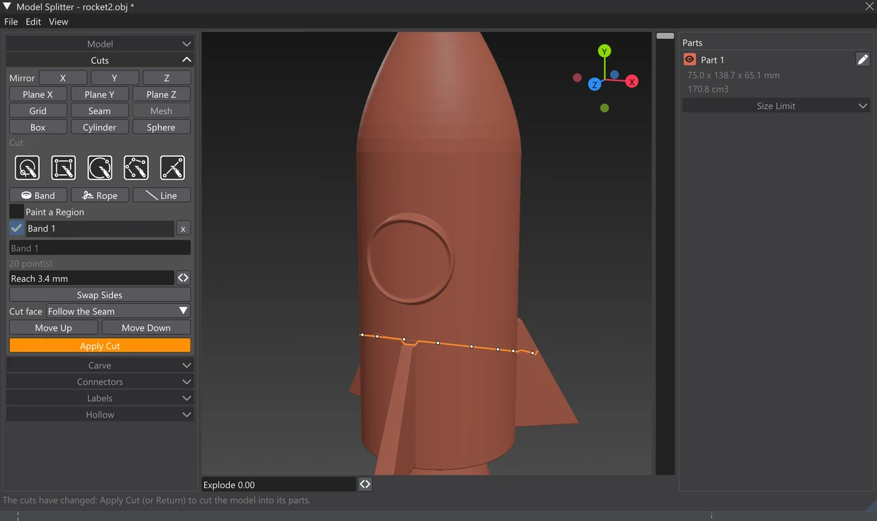
These three tools draw a seam straight onto the model by dragging, which is quicker than clicking points. Each one makes a seam cut with the settings above. Band and Rope lines are orange, and their points are white.
Band
Band draws a loop you can then push into place.
- Drawing it: drag on the model to pay the band out. Let go, turn the model with a right drag, and carry on: while the band is open, a press anywhere on the model continues it from where its line left off (a click adds one point, a drag adds a few). Bring it back to the white anchor, its first point, to close it. While it is open, a band is drawn but cuts nothing. Its points move one at a time, and right-clicking one deletes it.
- Editing it: once closed, the band is a smooth curve through a few points. Drag the orange line to reposition it, and the stretch either side follows up to the nearest pins. Click a point to pin it (pins are orange), and right-click a pin to release it. Pressing on the line between two points adds a point there. Drag to pull it, or just click to pin it.
- Dragging follows the held surface, so a point can be pulled round the side of a limb and on behind it. Alt-drag instead puts the point on the surface you can see under the pointer.
- Smoothing sets how much of the band eases out round a point you drag. At 0 only that point moves.
Rope
Rope is drawn the same way: drag to pay out the rope, let go, right-drag to turn the model, and carry on from the loose end (it is ringed). Bring it back to the white anchor to close it. The difference is in editing: drag any point on the rope to move it, and unlike a band, nothing either side follows. Right-click a point to delete it. A rope keeps the corners you draw, so it suits hard edges and panel lines. Remove Last and Clear Points work on a rope too.
Line
Line is the quickest. Draw one stroke across the model from one side to the other, and a closed band goes round the model under your stroke, through the front and the back. A straight stroke gives the model’s exact cross-section there. A curved stroke bends the band with it. The result is a band, so you can drag it about and pin it as above, with Line or Band out.
Follow Sharp Edges
While Band, Rope or Line is out, Follow Sharp Edges appears with an angle beside it (on, at 40°, to start). The seam then keeps to the model’s sharp edges, such as its corners and panel lines, wherever it comes near one, and turns their corners with them. The angle is how sharp an edge must be to count: the angle between the faces either side of it. A lower angle follows softer edges too. The edges it will follow are drawn faintly on the model while the tool is out. Pins stay where you put them. The shipped settings for these tools are in Settings > Model Splitter.
Paint a Region
Tick Paint a Region and paint over the model where a part should be. The painted faces show in violet. The outline of the painted region becomes the seam, so this is the easiest way to cut out an odd-shaped patch.
- Drag to paint. Ctrl+drag rubs out, and Alt+drag turns the view.
- Face Select paints only the faces the camera can see. Volume Select paints straight through the model, every face under the brush at any depth, including the back and hidden ones.
- The slider under them is the brush’s radius on the model, in mm. [ and ] change it (hold to repeat), as does Shift+wheel.
- Make Seams makes a seam of each outline of the painted region, then clears the paint. A patch gives one seam, and a band painted round a limb gives two. The painted side is side A. The seams are ordinary seams, so their points can be moved afterwards.
- Clear Paint (also in the Edit menu) wipes the paint without making anything.
Mirror
The Mirror buttons, X, Y and Z, at the top of the accordion, repeat every cut across a mirror plane. With two mirrors on, each cut is also repeated across both of them together. Make one cut on the left arm, and the right arm is cut too. A mirror starts through the model’s middle. In the view it is drawn as a line with two circles beside it, and dragging either circle moves the mirror along its axis. The mirrored copies are drawn faint violet. Grids are not mirrored, and a plane that lands on itself is not doubled.
The connectors on a mirrored plane cut are mirrored with it: each peg, dowel, magnet, key or dovetail is made again on the copy, its place, lean and turn reflected. On a plane that lands on itself — square to the mirror — a connector gets a twin on the same cut, unless it sits on the mirror line. The copies are numbered after the originals, so every joint keeps a number of its own.
The cuts list
- The tick box beside a cut switches it on or off. Switched off, the parts are worked out as if it were not there, and you can switch it back on at any time.
- Click a cut’s name to select it, and click it again (or press Escape) to let it go.
- The x button, or Delete with the cut selected, deletes it.
- Edit > Reset All Cuts takes every cut out, together with the connectors and cut-face labels on them, leaving the model whole again. It is one undo step.
- Edit > Undo (Ctrl+Z) and Redo (Ctrl+Y or Ctrl+Shift+Z) step through every change to the cuts. A whole drag counts as one step.
Moving round the model
The view follows Settings > Mouse Settings, as the main view does. A left drag on empty space turns the view (a left drag on the model belongs to whatever tool is out). A right drag turns it, a middle drag pans, and the wheel zooms toward what is under the mouse, so you can get close to a small detail. Ctrl+right click on the model makes that point the centre of the view and turns the view to face the surface there square on. This is handy before drawing a shape on a sloping face.
Keys
| Key | What it does |
|---|---|
| Return | Closes a Cut Poly being drawn, makes a marked cut, or applies the cuts (Apply Cut). |
| Escape | Drops a Cut Poly being drawn, or a marked cut. Otherwise it puts the Cut tool away, stops painting or drawing points, and finally lets go of the selected cut. |
| Delete | Deletes the selected connector, or else the selected cut. |
| Ctrl+Z / Ctrl+Y | Undo / Redo. With a shape marked, Ctrl+Z drops the mark first. On a Cut Poly it removes the last corner. |
| [ / ] | Smaller / bigger brush while painting a region. |
| Ctrl+right click | Centre the view on that point of the model and face it. |
Editions
- Every edition: planes, grids and Slice.
- Light, Vertexix and Ultra: Cut Lasso, Cut Box, Cut Circle and Cut Poly, the Box, Cylinder, Sphere and Mesh cutting solids, and the size limit (Fit to Size Limit, Cut a Grid That Fits).
- Vertexix and Ultra: Seam, Band, Rope, Line and Paint a Region.
Controls your edition does not have are greyed out, and their tooltips name the edition that has them. Free exports up to 4 parts and Light up to 16. If you open a working file made in a higher edition, the cuts your edition does not have are left out of the parts, and the window tells you so.