
Model Splitter
The Model Splitter cuts a model into parts you can 3D print one at a time, then joins the parts back together with pegs, dowels, magnet pockets or keys so they line up when you assemble them. It works in its own window, on its own copy of the model, in millimetres. When the parts are ready, Export Parts... writes them as 3MF, STL, OBJ or PLY files for your slicer.
Vertexix only deals with the model. It never slices, never adds supports and knows nothing about printers: it hands your slicer clean, closed solids, and your slicer does the rest.
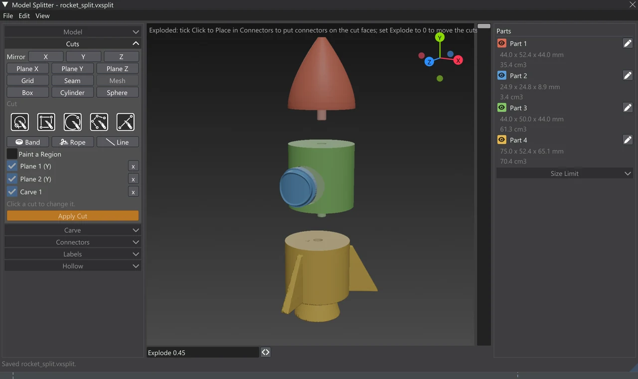
Opening the window
Choose Window > Model Splitter. The window opens on the model on screen: the Generated Mesh (every Sculpt mesh) when there is one, otherwise the Loaded Mesh. If the window already holds a model, it keeps it. You can bring in a different model at any time from the window’s File menu — see Bringing a Model In.
The splitter always works on a copy. Nothing you do in it changes the model you brought in: the original stays exactly as it was in the main view, and parts only come back to the Sculpt Tree when you send them there yourself.
The window floats over the app and does not dock. Drag it by its title bar to move it. The title shows the working file’s name (or the model’s) and a * while there are unsaved changes.
The window’s layout
- The menus. File holds the working file (Open..., Open Recent, Save, Save As...), the ways out (Export Parts..., Send Parts to Sculpt, Save Assembly Picture...), the ways in (Open Model..., Use the Loaded Mesh, Use the Selected Sculpt Meshes) and Close. Edit has Undo, Redo, Delete Cut, Reset All Cuts (every cut out at once, with its connectors and cut-face labels; Undo brings them back) and Clear Paint. View has Reset View, Show Wireframe and Show Thin Walls.
- The left column is a row of accordions, one open at a time: Model (the model’s size, its solid check, scaling and repairs), Cuts, Carve, Connectors, Make a Peg Shape, Labels and Hollow. Opening one closes the others. When a model comes in, Cuts opens — or Model, if the model has a problem that has to be repaired before it can be cut.
- The 3D view in the middle shows the parts, each in its own colour, with the Explode slider under it and the Cut Away slider down its right-hand side.
- The right column is the Parts list, with the Size Limit accordion under it.
- The status line along the bottom says what is happening: how many parts came from how many cuts and how long that took, that the cuts have changed and are waiting for Apply Cut, that the model must be a closed solid first, or a short notice about what you just did.
A recipe, applied with Apply Cut
The cuts, connectors, carves, labels and hollows you set up are a recipe, not a series of finished operations. Every cut can be moved, turned, switched off or deleted at any time, and every peg resized or moved. The parts are always worked out again from the original model with the recipe as it stands, so nothing is ever lost by changing your mind.
Nothing is cut until you ask. While you place and adjust cuts, the parts stay as they were and the status line says the cuts have changed. Press Apply Cut (at the bottom of the Cuts and Carve accordions) or Return to cut the model into its parts. Apply Cut also turns a shape still marked with a Cut tool into its cut, and closes a Band or Rope that is still open back to its anchor. Connectors and labels are different: they are worked out at once on the parts already cut, so you see a peg as soon as you place it.
Undo (Ctrl+Z) and Redo (Ctrl+Y or Ctrl+Shift+Z) step through changes to the recipe; a whole drag of a gizmo is one step. While the window has the keyboard, these keys are the splitter’s, not the main window’s. With a shape marked by a Cut tool, Undo first takes the mark away. Showing or hiding a part is not an undo step. Bringing in a new model, or changing its scale, starts the history afresh.
Moving around the view
The view uses the same mouse as the rest of Vertexix, as set in Mouse Settings:
- A left drag on empty space turns the view. On the model, the left button belongs to whatever tool is out (a cut shape, a seam point, a connector). Ctrl or Alt + left drag turns the view anywhere; Shift + left drag pans.
- A right drag turns the view and a middle drag pans, unless Mouse Settings binds those buttons to something else.
- The wheel zooms toward whatever is under the mouse, so you can get very close to a detail without passing into the model.
- With a drawing tool out (a Cut tool, Band, Rope, Line or the brush), a plain left drag always belongs to the tool and never turns the view.
- Double-click the view (when you are not painting), or choose View > Reset View, to frame the whole model again.
- Ctrl + right click on the model makes the point you clicked the centre of the view and turns the view to look straight at that surface, as it does in the main view. Useful before drawing on a curved area.
The view gizmo in the top-right corner is the same one the main view has (axis balls or a cube, as Settings > Interface sets it). Click an axis to look along it, or drag the gizmo to turn the view. Right-click it to switch between the two styles.
The Explode slider under the view pushes the parts apart from the model’s centre, each in proportion to how far it is from the middle, so you can see every part and its cut faces. It only moves them on screen: the parts themselves are not moved. While the parts are pushed apart, the cut planes, gizmos and connector marks are hidden (they would no longer line up), and a line of text over the view says what a click will do. With Click to Place ticked in the Connectors accordion, a click on a cut face of an exploded part places a connector there; pressing on the view with a drawing tool brings the parts back together first.
The Cut Away slider runs down the right-hand side of the view. At the top nothing is hidden. Drag it down and the model is hidden from the top down, as if a huge box were lowered onto it, until at the bottom it reaches the model’s lowest point. Where the box cuts through solid material, the inside is drawn flat in a darker shade of the part’s colour, so you can look at a hollow part’s wall, the sockets or a key’s groove. Double-click the slider to show the whole model again. Like Explode, it changes only the view: the parts, the exported files and the assembly picture stay whole.
View > Show Wireframe (or the app’s own Show Wireframe key, W unless you changed it in Keyboard Setting) draws every part’s edges over it. A model rebuilt with Field Remesh shows its even quads.
The Parts list
Every part the recipe makes has a row in the Parts list: its colour button, its name, its size (width × height × depth in mm) and its volume in cm³. Dowels, which are printed on their own, are listed as parts after the others.
- The colour button carries an eye. Click it to hide the part in the view (the eye is crossed out), and again to show it. A hidden part is still exported.
- The name picks the part: the others are dimmed toward grey, the cut that made the part is selected again (its plane and gizmo come back), and the Connectors list shows only the connectors on this part, each with the part it joins it to. Click the name again, or press Esc, to let it go. The Hollow accordion acts on the part picked here.
- The pencil on the far right opens Edit Part: a Name for the part and its Colour (click the swatch for any colour, or pick one of the twelve palette colours; Default Colour puts back the one it had). OK or Return keeps the changes, Cancel or Esc drops them; it is one undo step. The name is what Export Parts saves the part as, and the colour is used in the view, in a 3MF file and when the part is sent to Sculpt. Renaming a part never renumbers the others.
- “hollow” after the volume marks a part that has been hollowed.
- An orange “!” marks a part that is not a closed solid, or one bigger than the size limit. Rest the pointer on it to see which.
A part keeps its name and colour when you move the cut that made it. When a later cut splits a part in two, both pieces carry on from it.
Size Limit
The Size Limit accordion under the Parts list sets the largest a part may be, as modelled: a width, height and depth in mm, typically your printer’s build volume. 0 means no limit on that side. Any part bigger than the limit is marked with a “!” in the Parts list. Cut a Grid That Fits adds a grid cut (or refits the first one) with the fewest cells that keep every part within the limit — see Cuts. The size limit is part of the Light edition and up.
A typical session
- Open the window with the model on screen, or use File > Open Model... for a file on disk.
- Answer the Change Model Size prompt with the size you want the printed model to be.
- If the Model accordion says the model is not a closed solid, repair it.
- Add cuts where you want the model to come apart, and press Apply Cut.
- Check the Parts list: every part closed, none over the size limit.
- Place connectors on the cut faces so the parts line up, and optionally label the parts or hollow the big ones.
- Push the parts apart with the Explode slider and look them over; use Cut Away to check inside.
- Save the working file so you can come back and change anything, then use Export Parts... to write the files for your slicer.
Keys
These work while the Model Splitter window has the keyboard.
| Key | What it does |
|---|---|
| Return | Apply Cut. With a shape marked by a Cut tool, make that cut; with a polygon being drawn, close it. |
| Esc | Drop a marked shape or a polygon being drawn, then put the tool away, then let go of the selected connector, part or cut. |
| Delete | Delete the selected connector, or else the selected cut. |
| Ctrl+Z | Undo (a marked shape’s mark first). |
| Ctrl+Y / Ctrl+Shift+Z | Redo. |
| Ctrl+S / Ctrl+Shift+S | Save / Save As the working file. |
| Ctrl+O | Open a working file. |
| W | Show Wireframe on or off (the app’s own binding). |
| [ / ] | Smaller / larger brush while painting a region. |