
Labels & the Assembly Picture
Once a model is in a dozen pieces, telling which goes where is half the job. Labels engrave part numbers or names into the parts — usually on a cut face, where they are hidden once the model is put together — or anywhere on the surface, cut in or standing out. Connector numbers pair up the pegs and sockets, and the assembly picture gives you a picture of every part pushed apart with its number, to build the model from.
Labels use the Text tool’s fonts, and are cut into the solid exactly, so they print as cleanly as any other detail. Like everything in the splitter, they are part of the recipe: change the words, size or place at any time and the parts are worked out again.
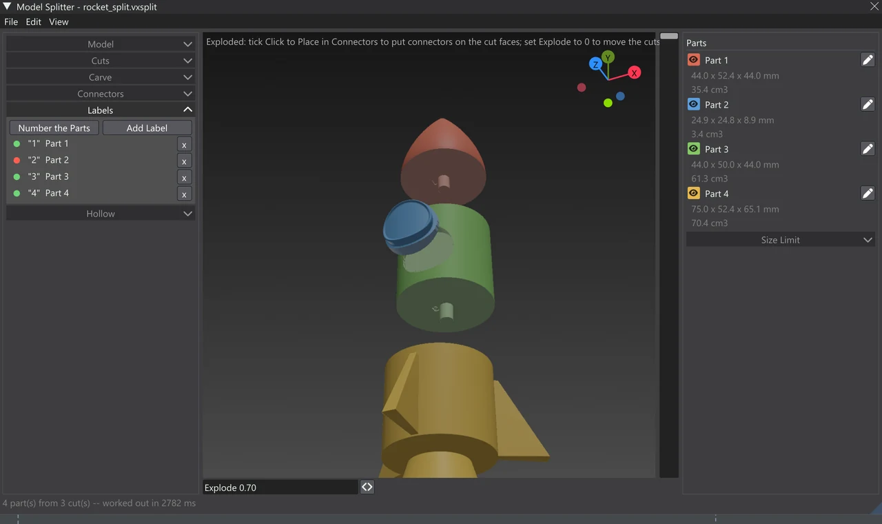
Numbering every part
Open Labels in the window’s left column and press Number the Parts. Each part gets its number engraved on its largest cut face. Parts that already have a label of their own are left as they are, so you can name a few parts by hand and number the rest. The numbers match the ones in the assembly picture.
Adding a label
Add Label adds a label reading “Label” on the first part’s largest cut face. Select it in the list to change its words, the part it goes on, or to place it on the surface instead.
The list shows every label with its words and where it goes, and a coloured dot: green when it fits, amber when it was made smaller to fit, red when it was not made. Click a row to select it, click again to let go; the x beside a row deletes that label. In the view each label is outlined by a box in the same colour (labels on hidden parts are not shown).
A label’s settings
| Control | What it does |
|---|---|
| Its words | The text engraved: a number, a name, a short note like “L arm”. |
| Font and style | Two dropdowns: the font, then its style (Bold is picked when the font has one). They are the Text tool’s fonts. A bold, plain font engraves and prints the most cleanly. |
| Size | The text’s size (its font size), in mm. On a cut face it is made smaller, down to half, if it does not fit. |
| Depth / Height | How deep the letters are cut in — or, for a raised label, how far they stand out. |
| Turn | Turns the text on the surface, from upright. |
Where a label goes
The dropdown under the settings says where the label goes:
- A part’s largest cut face (“Part 3: its largest cut face”) — the label is centred on that face, or moved to the nearest place where it fits with a margin in from the edge. Sockets, peg roots and connector numbers on the face count as holes, so the label keeps clear of them. It reads upright from outside the part, never mirrored, and is always cut in: a cut face has to stay flat to meet its partner. Once the parts are put together it is hidden inside.
- On the surface (click to place) — anywhere on the model’s outside. Choose it, or press Place on the Surface, then click on the model: the label goes there, facing out and upright. The button reads Click on the Model... while it waits; Esc stops. If no label is selected, the click makes a new one reading “1”. On a curved surface the letters reach far enough that every one of them cuts.
Raised (surface labels only) makes the letters stand out of the surface rather than cut into it — a badge, a signature, a name plate.
When a label does not fit
The selected label’s state is written under its settings:
| It says | What to do |
|---|---|
| It fits. | Nothing: it is made at its full size. |
| “Made at 72% of its size to fit.” (amber) | The face was too small, so it was made smaller (to 72%, 60% or half). Fine if it is still readable; otherwise use fewer or shorter words, or a smaller Size so you choose the size, not the splitter. |
| Not made: it does not fit the cut face even at half size. (red) | Shorten the words, lower the Size, or place it on the surface instead. |
| Not made: its part is gone, or the point is off the model. (red) | The part it was on no longer exists (a cut was deleted), or a surface label’s point no longer meets the model. Pick another part, or place it again. |
| It has no words. | Type some. |
Labels and later cuts
A label follows its part through later cuts: cut a labelled part in two and the label moves onto the larger of the two pieces, so numbering early does not have to be redone. Reset All Cuts in the Edit menu takes out the labels on cut faces along with the cuts (Undo brings them back); labels on the surface stay.
Connector numbers
Separate from labels, Number Them in the Connectors accordion engraves each connector’s number beside it on both faces it joins, at the size you set beside it. Each copy reads from its own side, so the “3” beside a peg goes to the “3” beside its socket. Labels on the same face keep clear of these numbers.
The assembly picture
Save Assembly Picture... in the window’s File menu saves a 2048 × 2048 pixel PNG of the parts pushed apart, seen from the direction the view is looking, drawn back until every part is in the picture. Each part carries its label’s words or its number, and a part you renamed in the Parts list has its name written beneath. Dowels are marked D. The parts are always shown whole, whatever the Cut Away slider is set to.
It is the order to put the parts together in: print it, or keep it with the exported files. Turn the view first so the parts you care about face you. The menu item is greyed until the parts are up to date with the cuts (press Apply Cut first).
Tips
- Engrave at least two layers deep: with 0.2 mm layers, a 0.4–0.6 mm Depth reads well. Very shallow labels vanish into the layer lines.
- Keep text no smaller than about 4–5 mm on an FDM printer; resin printers manage smaller.
- Text on a face that prints facing up or upright is crispest. Text on a face printed facing down sits on supports.
- Short words read best: numbers, or two or three letters.
Editions
The Labels accordion and connector numbers (Number Them) are in the Vertexix (regular) and Ultra editions. A working file with labels opened in Free or Light is cut without them, and the window says so.