
Connectors & the Peg Editor
A connector is what holds two parts together across a cut: a Peg standing out of one part into a socket in the other, a Dowel printed on its own with a socket in both parts, a pocket for a Magnet on each side, a Key — a lip running all round the cut face with a groove for it in the other part — or a Dovetail, a rail the parts slide together along. Connectors sit on plane cuts, and they are part of the recipe like the cuts are: you can resize, move, re-shape or delete any of them at any time, and the parts are worked out again.
The rule behind every connector is simple: the socket is the peg grown by the fit gap, all round, whatever its shape. You never set two sizes and try to keep them in step — you set the peg and the gap, and the socket follows.
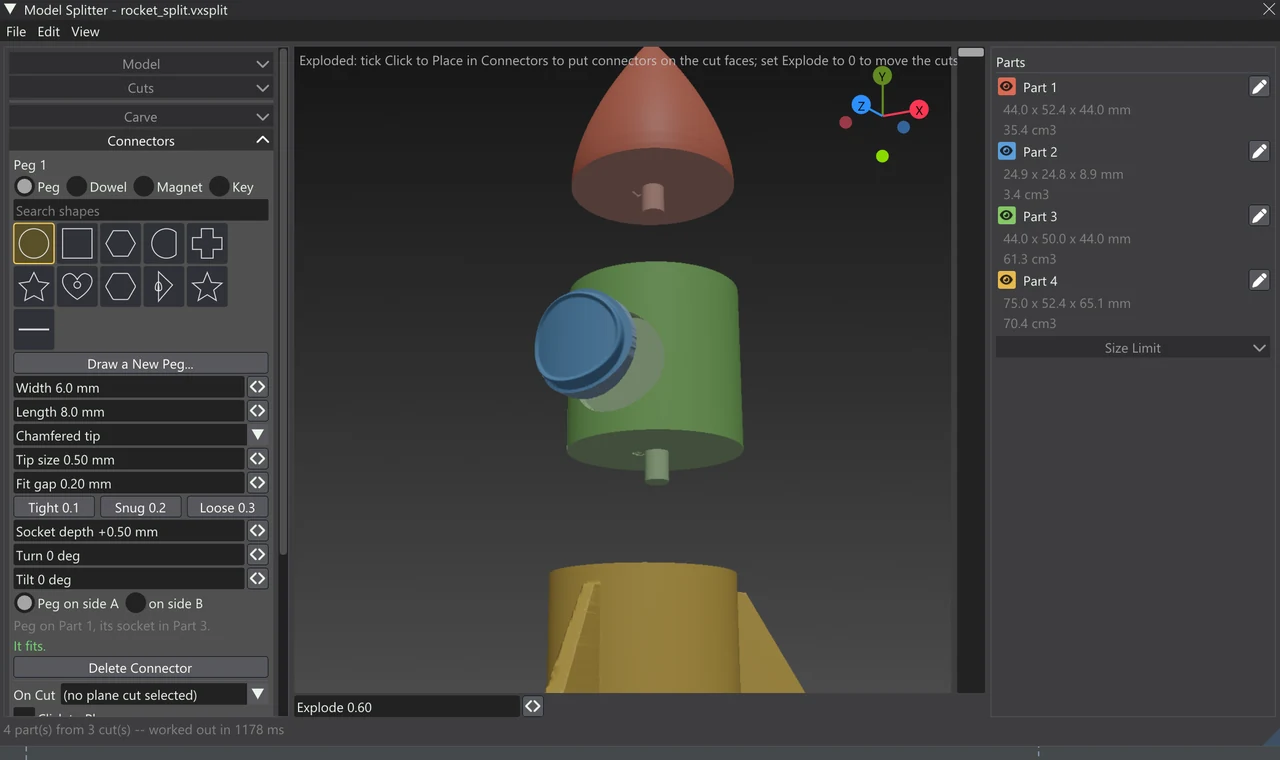
The Connectors accordion
Open Connectors in the window’s left column. Its controls change the selected connector; with none selected, the line at the top reads Settings for the next one placed and the controls set up the next one you place. Change a selected connector and its peg and its socket change together — they are one connector, not two.
The defaults are a round peg 6 mm across and 8 mm long, a 0.5 mm chamfered tip, a 0.2 mm fit gap and a socket 0.5 mm deeper than the peg. You can change what a new model starts with in Settings > Model Splitter (see Saving, Exporting & Sending to Sculpt).
Kinds of connector
| Kind | What it makes | When to use it |
|---|---|---|
| Peg | A pin on one part, a socket in the other. | Most joins. Nothing extra to print or buy. |
| Dowel | A separate pin, printed on its own, with a socket in both parts. The dowel is a part of its own (“Dowel 1”), listed last and exported like any other part. | When neither part should carry a pin — a peg standing proud can snap off or need supports. A dowel printed lying down is also stronger along its length. |
| Magnet | A round pocket in each part for a magnet. Its sizes are the magnet’s Diameter and Thickness (6 × 3 mm to start); each pocket is one magnet’s thickness deep, plus a glue gap. | Parts you want to take apart again: a lid, a removable head, a display piece. |
| Key | A lip all round the cut face, in from its edge, and a groove for it in the other part. | Thin walls and hollow parts, where a peg has no material to sit in. See Keys. |
| Dovetail | A rail right across the cut face, wider at its top than at the face, in a groove of its shape in the other part. | Parts that should slide together and stay together without glue: they cannot be pulled apart along the cut. See Dovetails. |
Choosing a peg’s shape
Pegs and dowels take their shape from the picker under the kind buttons: a grid of outlines, the picked one framed in yellow. Rest the pointer on one for its name.
- Built in: Round, Square, Hex, D shape (a round peg with a flat side, so it cannot turn), Cross and Star. Anything that is not round also stops the parts turning on the peg, so one non-round peg is often enough.
- Your Peg Library: the shapes you have made with Make a Peg Shape or drawn in the Peg Editor, after the built-ins. A peg you drew and saved with its own sizes brings them with it when you pick it.
- The recipe’s own: a working file opened from someone else carries the pegs it uses, so they show here even when they are not in your library.
Once there are more than eight shapes, a search box (Search shapes) appears above the grid. Right-click a shape for more:
- Edit... — one of your own: opens it in the Peg Editor.
- Duplicate... — any shape, built-ins included: opens a copy in the Peg Editor, to change and save under a new name.
- Delete from the Peg Library — one of your own.
Draw a New Peg... under the grid opens the Peg Editor on an empty canvas.
Sizes and fit
All lengths are millimetres. The sliders take a typed number too.
| Control | What it does |
|---|---|
| Width | How wide the peg is across its larger side. For a magnet: Diameter, the magnet’s. |
| Length | How far the peg reaches into the other part. For a dowel, its whole length: half of it goes into each part. For a magnet: Thickness, one magnet’s. |
| The tip | How the end finishes (a dowel: both ends): Chamfered tip (the default), Flat tip, Rounded tip, Tapered all along (the peg narrows straight from root to end), or Tapered all along, chamfered tip. A chamfered or rounded end finds its socket more easily. The socket always stays straight. |
| Tip size | For a chamfered or rounded tip: how much the end is narrowed, in mm. |
| Tip % as wide | For a tapered peg: how wide the end is, as a share of the root. |
| Fit gap | The space all round between the peg and its socket. Tight 0.1, Snug 0.2 and Loose 0.3 set it in one click. 0.2 mm suits most printers; less is tighter. |
| Socket depth | How much deeper the socket is than the peg is long, so the parts close fully even if the tip prints a little long or there is glue in the hole. For a magnet this is the glue gap at the bottom of each pocket. |
| Turn | Turns the peg about its own axis — which way round a D, a cross or a star sits. |
| Tilt | Leans the connector away from square to its cut (up to 45°). Useful when the part beyond the cut leans, so the peg runs down its middle. |
| Peg on side A / on side B | Which part carries the peg: A, the side the cut’s arrow points to, or B. The other part gets the socket. |
With a connector selected, a line under the controls says which parts it joins, for example “Peg on Part 1, its socket in Part 2.”
Placing connectors
On Cut
On Cut is the plane cut the connectors go on. It lists the enabled plane cuts; with a part picked in the Parts list, only the cuts that part has a face on. Picking a part in the Parts list also selects one of its cuts for you. Connectors sit on plane cuts only — not on grids, cutting solids, seams or carves.
Click to Place
Tick Click to Place, then click in the view:
- With the parts together, a click inside the On Cut plane’s outline puts a connector there.
- With the parts pushed apart (Explode above 0), a click on any part’s cut face puts one there — on whichever plane cut that face belongs to, which then becomes the On Cut cut. This is often the easier way: you can see the face you are clicking. A face turned away behind its own part cannot be clicked through it.
A drag still turns the view, so you can keep placing and looking. Ticking Click to Place puts the cut-drawing tools down, so their clicks do not get in the way. The banner over the view says what a click will do.
Moving and deleting
With the parts together, press on a connector and drag to slide it across its cut face. (On the parts pushed apart the connector marks are not drawn, so they cannot be dragged there.) Delete Connector, the x beside it in the list, or the Delete key removes the selected one. Every change is a step Undo takes back.
Auto Place
Set how many you want (1 of them to start, up to 12) and press Auto Place: that many connectors, with the settings above, are spread over the On Cut face, kept in from its edge by half their width plus the fit gap plus the least wall, each put where there is the most room. Connectors you placed by hand stay where they are, and the new ones keep clear of them.
The list
Under the placing controls every connector is listed with a coloured dot for its checks (below). Click a row to select it; click it again to let go. With a part picked in the Parts list, only that part’s connectors are listed, each with the part it joins it to (“Peg 2 → Part 4”), and a line counts them; Show All lets the part go and lists them all again.
The checks
Every connector is checked against the parts as the cuts left them, and coloured in the view and in the list:
| Colour | What it found |
|---|---|
| Green | It fits. The peg stays inside its part, the socket leaves enough wall, and it does not run into another connector. |
| Amber | Its socket leaves too thin a wall before the surface — it would be made, but the part may crack or show the socket through. |
| Red | It is not on the cut face (so it is not made: drag it onto the cut), it comes out of the part (move it in from the edge, or make it smaller), or it runs into another connector. |
The selected connector’s finding is written out under its controls. Least wall (1.2 mm to start) at the bottom of the accordion is the least material a socket may leave before the part’s surface; anything thinner is marked amber. Set it to what your printer can make solid — two or three line widths is a good start for plastic.
Keys
A Key runs a lip all round the cut face, in from its edge, raised into the other part, which gets a matching groove grown by the fit gap. Every separate region of the face gets its own ring. It needs very little material, so it suits thin shells and hollow parts, and it lines the parts up all the way round, not only at a few points.
- Lip width — how wide the lip is (2 mm to start).
- Lip height — how far it stands up into the other part (2 mm).
- Inset — how far in from the cut face’s edge the lip runs: the groove’s wall to the outside (1.5 mm).
- Square (straight sides) or Tapered (stepping in to 60% at the top, so it finds its groove and prints without support).
- Lip on side A / on side B — which part carries the lip.
The fit gap and socket depth work as for a peg. A key is not placed by clicking: select a plane cut (in On Cut) and press Add a Key to the Selected Cut. Keys have no point to drag. Its checks: the cut must have a face with room for the lip; every part of the face must be big enough for it (else less inset or a narrower lip); and the groove must leave at least the least wall to the outside (else more inset).
When you tick Hollow This Part on the Hollow accordion, the next connectors switch from Peg to Key, since a hollow’s wall has no room for a peg; a notice says so. Pick Peg again to change that.
Dovetails
A Dovetail is a sliding joint. One part carries a straight rail that runs right across the cut face and out at both ends; the rail is narrowest where it leaves the face and flares out towards its top, and the other part gets a groove of the same shape, grown by the fit gap. The parts slide together along the rail, and once together they cannot be pulled apart along the cut — only slid back out. (A key’s closed ring could never be a dovetail: there would be no way to slide it in.)
- Width at the face — the rail’s width where it leaves the cut face, its narrowest (6 mm to start).
- Height — how far it stands up into the other part (4 mm).
- Flare — how much wider it gets towards its top, on each side (15°). This is what holds the parts together: 0° is a straight rail that only guides the slide; 10–20° holds well, and prints without supports when the rail points up.
- Turn — which way the rail runs across the face: the way the parts slide together. Choose a way that leaves the slide clear of the rest of the model.
- Rail on side A / on side B — which part carries the rail.
A dovetail is placed like a peg — Click to Place, or dragged — and has no tilt, since a leaning rail would wedge the slide. The fit gap and socket depth work as for a peg. Its checks: the other part must have material where the rail is to slide into it, and the groove must not cut the other part in two (a lower rail, or another place, if it does). A dovetail is in the Vertexix and Ultra editions, with keys.
Numbering connectors
Tick Number Them and each connector’s number is engraved beside it on both faces it joins, at the size beside the tick (3 mm to start). Each copy reads from its own side, so when the parts are in your hand, the “3” on one face goes to the “3” on the other — useful when a model has many similar cuts. See also Labels for numbering whole parts.
Make a Peg Shape
The Make a Peg Shape accordion, at the bottom of Connectors, makes a peg from numbers instead of drawing it. Pick a kind and set its numbers; a preview shows the outline.
| Kind | Its numbers |
|---|---|
| Polygon | How many sides (3–64) and corner rounding. Six sides is a hex peg; many sides with rounding is a soft-cornered shape. |
| Star | How many points, how deep the inner corners go, and corner rounding. |
| Rectangle | Its width / height ratio and corner rounding. A flat bar for a thin part. |
| D shape | How deep the flat side is. |
| Cross | How wide its arms are. |
Type a Name and press Save to the Peg Library: the shape is saved for every project and picked for the next connector.
The Peg Editor
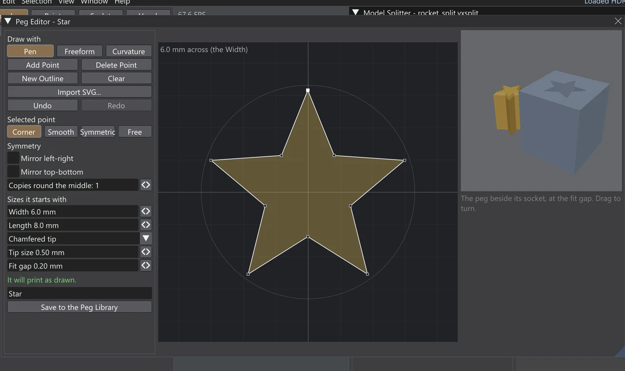
The Peg Editor is a window of its own for drawing a peg’s outline with the app’s bezier pens — a shape that keys into place one way only, a logo, a gear. Open it with Draw a New Peg..., or right-click a shape in the picker and choose Edit... or Duplicate.... It has three panes: the tools on the left, the drawing canvas in the middle, and a 3D preview on the right.
Drawing
Under Draw with are the five pens, the same as everywhere else in Vertexix; the number keys 1–5 pick them while the window has focus.
| Pen | Key | What it does |
|---|---|---|
| Pen | 1 | Click for a corner point, click and drag for a smooth one. Click the first point again to close the outline. |
| Freeform | 2 | Drag to draw freehand; the line becomes a closed outline of smooth points. |
| Curvature | 3 | Click points and the curve flows smoothly through them; Alt+click for a corner. |
| Add Point | 4 | Click a span to add a point there, without changing the shape. |
| Delete Point | 5 | Click a point to remove it. |
Drag a point to move it: with Shift it moves slowly, with Ctrl along one axis, and it snaps into line with other points (a blue guide shows it; hold Alt to move freely). Delete removes the selected point and Esc lets it go. The mouse wheel zooms the canvas and a middle drag pans it. Undo and Redo (Ctrl+Z / Ctrl+Y) step through the drawing; Clear empties it.
The canvas has a millimetre grid at the peg’s Width and a circle the drawing is sized to; whatever you draw is scaled so its larger side is the Width across, shown in the corner (“6.0 mm across (the Width)”). The shape as it will be made is filled in yellow.
Outlines and holes
New Outline makes the next point start another outline. An outline drawn inside another is a hole — a hollow peg or a tube; one inside a hole is solid again. Outlines side by side make a peg in several pieces.
The selected point
Under Selected point, four buttons set how its handles behave:
- Corner — no handles: a sharp corner.
- Smooth — handles in line, each its own length: the outline turns smoothly.
- Symmetric — handles in line and the same length.
- Free — each handle on its own: a corner with curves either side.
Symmetry
Under Symmetry, Mirror left-right and Mirror top-bottom mirror what you draw, and Copies round the middle repeats it round the centre — draw one tooth and get a gear. The filled shape shows the result as you draw.
Import SVG
Import SVG... brings in the closed shapes an SVG file draws — paths, rectangles, circles, ellipses and polygons — as outlines you can edit, scaled to the circle and centred. Curves come in as curves, with their handles. A logo from a drawing program, or a shape from a vector library, becomes a peg this way. It is one step for Undo.
What the checks say
- It will print as drawn. — all is well.
- A closed outline is needed: three points or more.
- Too thin: part of it is thinner than twice the fit gap. The socket’s rounding would swallow that detail, so the spot is ringed in red. Make it wider there.
- Crosses itself: an outline crosses itself, and every part it closes is filled. Usually a sign a point has been dragged across a span.
Sizes it starts with
Under Sizes it starts with are the Width, Length and tip the peg is saved with; picking the peg in Connectors later brings these sizes. The Fit gap here is only for the checks and the preview — each connector keeps its own.
The 3D preview
The right-hand pane shows the peg beside a block with its socket, at the fit gap, so you can see both before you save. Drag in it to turn it.
Saving
Type a Name and press Save to the Peg Library. If a peg of that name is already in your library the button reads Save, Replacing That Peg. Saving picks the peg for the next connector, and a recipe that already uses a peg of that name is updated to the new shape (one Undo step).
The Peg Library on disk
Each saved peg is one small .vxpeg file in the Pegs folder of your Vertexix library (in your user data folder), holding its outline, tip and sizes. Pegs are shared by every project, and you can copy the files to another computer. A .vxsplit working file also carries the pegs it uses, so it opens elsewhere without your library.
Tips for a good fit
- Print a test first. Cut a small cube in two, put one peg in it, and try Tight, Snug and Loose. The right gap depends on your printer, material and how the part lies on the bed.
- Give pegs a chamfered or rounded tip and a little socket depth; the first layers of a socket often print slightly small.
- Two round pegs, or one non-round one, stop parts turning. A single round peg lets them spin.
- Keep pegs green. An amber connector may print, but the thin wall it leaves is where the part will split.
- For magnets, mark which way round each one goes before gluing: a magnet glued the wrong way pushes its partner away.
- On thin or hollow parts, use a Key instead of pegs.
Editions
Pegs — the built-in shapes, shapes made with numbers, and drawn pegs with the Peg Editor and SVG import — are in every edition, Free included. Dowel and Magnet are in Light and up. Key, Dovetail and Number Them are in the Vertexix and Ultra editions. A working file from a higher edition opens in a lower one, but the connectors that edition lacks are left out of the parts, and the window says so.