
Saving, Exporting & Sending to Sculpt
The Model Splitter keeps two very different things apart. Save writes your working file: the model and the whole editable recipe, so you can come back and move a cut or resize a peg later. Export Parts... writes the files for your slicer: finished solids, one per part or all in one 3MF, with nothing left to edit. A third way out, Send Parts to Sculpt, puts the parts back into Vertexix’s Sculpt Tree to be sculpted, painted or retopologised further. All three are in the window’s File menu.
The working file (.vxsplit)
Save (Ctrl+S) and Save As... (Ctrl+Shift+S) write a .vxsplit file. It holds everything needed to carry on exactly where you left off, with no other file:
- the model itself, in millimetres, with its colours;
- the whole recipe: every cut, carve, seam and mirror, every connector, label and hollow, all still editable;
- each part’s name, colour and whether it is hidden, the size limit and your Export Parts choices;
- the peg shapes the recipe uses that are not built in, and the outlines of the labels’ text, so the file opens and cuts the same on another machine without your Peg Library or fonts.
Open... (Ctrl+O) reads a .vxsplit back. Open Recent lists the last ten working files, newest first; rest the pointer on one to see where it is, and Clear the List empties it. A file that is no longer on disk drops off the list.
While the work has changes you have not saved, the window’s title ends in *. Before anything would throw those changes away — Open..., a recent file, bringing in a new model, Close, the window’s close box, or quitting Vertexix — the Unsaved Changes prompt asks first: Save, Don't Save or Cancel.
When you save a Vertexix project (.vxp), the splitter’s work goes into it too, and comes back when the project is opened. A project saved without splitter work empties the splitter when it is loaded, because that work belonged to the document being replaced. The window’s own Save still writes a separate .vxsplit whenever you want one. See Projects & File Types.
Export Parts
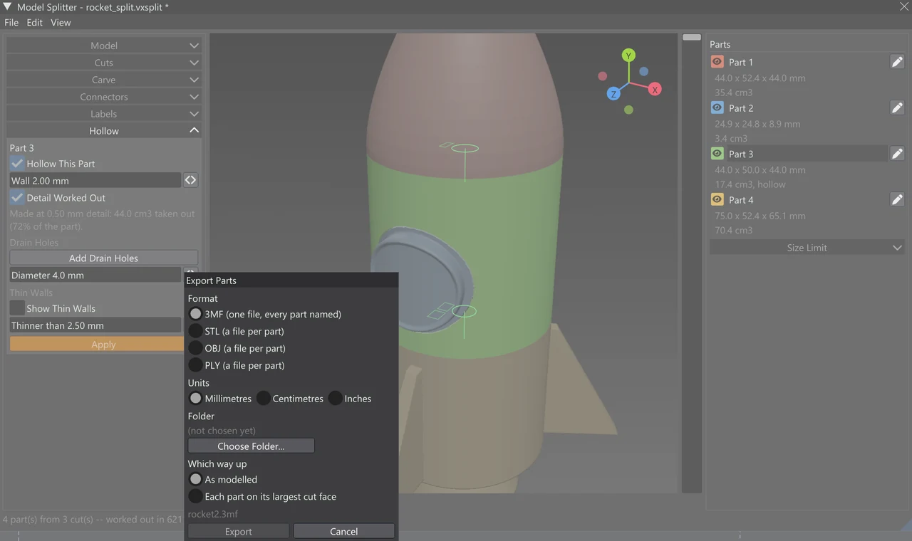
Export Parts... opens a dialog for the files your slicer will read. It is greyed until the parts on screen match the recipe: if the cuts have changed, press Apply Cut first (rest the pointer on the menu item to see why it is greyed).
| Control | What it does |
|---|---|
| Format | 3MF (one file, every part named): one file holding every part as an object of its own, with its name and colour — what most slicers handle best, and the default. STL (a file per part), OBJ (a file per part) and PLY (a file per part) write one file for each part; PLY also carries colour per point. |
| Units | Millimetres (the default), Centimetres or Inches. A 3MF file says which unit it uses. STL and OBJ files have no unit, and slicers read their numbers as millimetres, so keep millimetres unless the program the files are for wants something else; the dialog warns you when you pick another. |
| File names | The name pattern for a file per part (not shown for 3MF): {model} is the model’s name, {n} the part’s number (01, 02, ...), {part} its name. The default {model}_{n} gives rocket_01.stl, rocket_02.stl, ... A part you renamed in Edit Part is saved under its name in place of its number. A pattern without {n} or {part} is numbered anyway, two parts of the same name never share a file, and characters Windows does not allow in a file name become _. |
| Folder | Where the files go. Choose Folder... picks it; Export stays greyed until one is chosen. The folder is remembered in the working file. |
| Which way up | As modelled keeps every part the way it sits in the model. Each part on its largest cut face turns each part over onto its largest flat cut face, resting at height 0 — usually the flattest side to print on. This is only a convenience for placing parts on the build plate; your slicer can still turn them any way. |
Under the settings, the dialog lists the first file names it will write and, in orange, how many of those files are already in the folder. Files are never overwritten silently: with existing files the button reads Replace and Export instead of Export. Cancel or Esc closes the dialog; your choices are kept either way.
Dowels are exported as parts of their own, since they are printed separately. In a file per part, identical dowels go out once, named with how many you need: rocket_dowel_x4.stl (two different sizes give _dowel1_x2 and _dowel2_x3). A 3MF keeps every dowel, since it is one build plate.
Every part is exported, including parts hidden in the view. Export always works at full detail: if the view shows the lighter preview of a big model, the full-detail parts are worked out first. The status line then says how many parts went into how many files, and where.
Send Parts to Sculpt
Send Parts to Sculpt adds the parts to the Sculpt Tree as new meshes, so you can carry on working on them with Vertexix’s other tools. They go into a Sculpt Layer of their own named Split: <model>, scaled back from millimetres to the Sculpt Tree’s metres, each with a material in its part’s colour, all as one undo step. Nothing already in the Sculpt Tree is changed. A model rebuilt with Field Remesh arrives as quads. Like Export, it always uses the full-detail parts.
The sent meshes are copies: changing the recipe afterwards does not change them. If you send again from the same model, the splitter asks what to do with the earlier ones: Replace Them (the earlier parts are taken out and the new ones put into the same layer, still one undo step), Add Alongside (a new, numbered layer), or Cancel.
The assembly picture
File > Save Assembly Picture... saves a 2048-pixel PNG of the parts pushed apart, seen from the view’s direction, with each part’s number or label on it: a guide to putting the print together. See Labels & the Assembly Picture.
Settings > Model Splitter
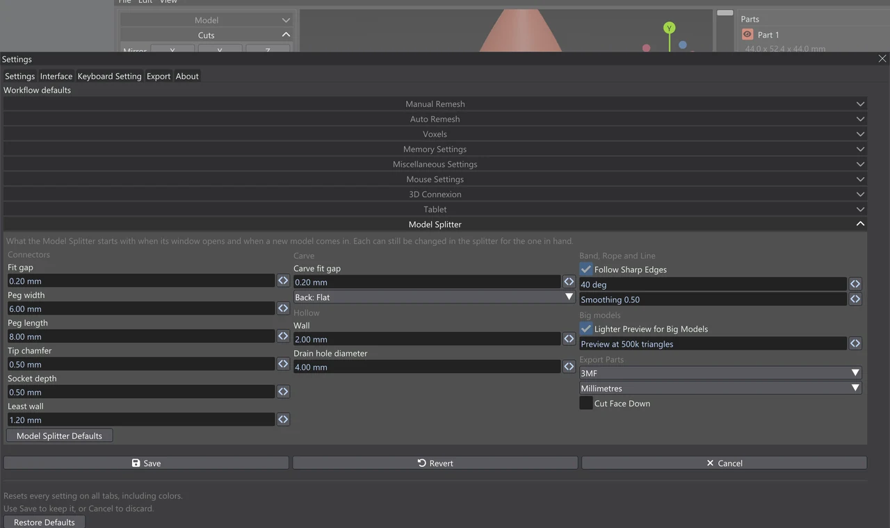
The Model Splitter accordion on the Settings tab holds what the splitter starts with. Its values are used when the splitter’s window opens and when a new model comes in; each can still be changed in the splitter for the model in hand.
| Setting | What it sets | As shipped |
|---|---|---|
| Fit gap | How much bigger a socket is than its peg, all round. | 0.2 mm |
| Peg width / Peg length | A new peg’s width across, and how far it reaches into the other part. | 6 mm / 8 mm |
| Tip chamfer | How much a new peg’s tip is narrowed, so it finds its socket. | 0.5 mm |
| Socket depth | How much deeper a socket is than its peg is long, so the parts close fully. | 0.5 mm |
| Least wall | The least material a socket must leave before the part’s surface; less is marked amber by the connectors’ check. | 1.2 mm |
| Carve fit gap | How much smaller a carved piece is made round its sides and back, so it presses back into its hole. | 0.2 mm |
| Back: Flat / Back: Follows the Surface | A new carve’s back. | Flat |
| Wall | The wall a part is left with when Hollow This Part is first ticked. | 2 mm |
| Drain hole diameter | A new drain hole’s diameter. | 4 mm |
| Follow Sharp Edges, its angle and Smoothing | Whether Band, Rope and Line snap onto the model’s sharp edges, at what angle an edge counts as sharp, and how much a Band eases out round a dragged point. | On, 40°, 0.50 |
| Lighter Preview for Big Models and its size | The lighter preview and the triangle count above which it is used. | On, 500k |
| Export Parts format and units, Cut Face Down | The Export Parts dialog’s format, units and which way up. | 3MF, Millimetres, off |
Model Splitter Defaults puts every one of these back as Vertexix ships them. The fit gap and peg sizes are explained in Connectors & the Peg Editor, the carve settings in Carve, the wall and drain holes in Hollow, Drain Holes & Thin Walls, and the edge following in Cuts.
Editions
Every edition has the Model Splitter. The table shows what each one includes; Editions Compared covers the rest of Vertexix. In the window, a feature your edition does not include is greyed, with the edition that has it in its tooltip or on a lock beside the accordion’s controls.
| Feature | Free | Light | Vertexix | Ultra |
|---|---|---|---|---|
| The Model Splitter window, repairs, Field Remesh, the working file | ✓ | ✓ | ✓ | ✓ |
| Plane, grid and Slice cuts, Mirror | ✓ | ✓ | ✓ | ✓ |
| Pegs, the fit gap, peg shapes made with numbers and drawn in the Peg Editor | ✓ | ✓ | ✓ | ✓ |
| Export Parts as 3MF, STL, OBJ and PLY; Send Parts to Sculpt | ✓ | ✓ | ✓ | ✓ |
| Dowels and magnet pockets | ✗ | ✓ | ✓ | ✓ |
| Cutting solids (box, cylinder, sphere, a Sculpt mesh) and the Cut tools’ Lasso, Box, Circle and Poly | ✗ | ✓ | ✓ | ✓ |
| Size limit | ✗ | ✓ | ✓ | ✓ |
| Seam cuts: Band, Rope, Line and painted regions | ✗ | ✗ | ✓ | ✓ |
| Keys | ✗ | ✗ | ✓ | ✓ |
| Labels and connector numbers | ✗ | ✗ | ✓ | ✓ |
| Carve | ✗ | ✗ | ✓ | ✓ |
| Hollow and drain holes | ✗ | ✗ | ✗ | ✓ |
| Thin-wall check | ✗ | ✗ | ✗ | ✓ |
| Parts exported or sent to Sculpt at once | 4 | 16 | Unlimited | Unlimited |
The part count includes dowels. With more parts than your edition allows, Export Parts and Send Parts to Sculpt refuse, and the status line names the edition that takes that many. A working file made in a higher edition still opens: what your edition does not include is left out when the parts are worked out (a carve is not carved, a hollow part stays solid, and so on), and the window says so.